
Fusion
DEMO Balance of Plant
In this area, KIT-INR experts continue the investigation on the Power Conversion System of a Fusion Power Plant started in 2011 with POF-III leading to a modular concept of the Helium Primary Heat Transfer System (PHTS). The Balance of Plant (BoP) design combines the Power Conversion System with the integration of a thermal energy storage device for compensating the pulsed operation of the tokamak (see Fig. 1) from the needs of the grid.
This activity is supported by the EUROfusion Power Plant Physics & Technology (PPPT) Work Program focused on the DEMO Balance of Plant.

Fig. 1. Simplified Fusion Power Plant (FPP) schematics
The task of the Balance of Plant is to use heat from different sources such as Breeding Blanket (BB), Divertor (DIV), and Vacuum vessel (VV) and transform it to electricity, to demonstrate power plant adequacy of fusion as a dedicated follow-up of ITER.
Our contribution started with a review of the overall DEMO concept to define essential interfaces and requirements for BoP. Compared to other energy conversion systems, the internal energy need of a fusion reactor is very high, so that energy harvesting becomes indispensable. As a typical crosscutting subsystem, BoP has multiple interfaces to other subsystems as shown in Fig. 2. Here the relationships are also visible; solid lines indicate exchange of mass and/or energy, dashed lines indicate logic or electric interfaces.

Fig. 2. Interaction of BOP with other DEMO sub-systems
Balance of plant (BoP) is composed of the primary heat transfer system (PHTS), an intermediate heat and storage system (IHTS) with an thermal energy storage system (ESS) to cope with dwell times (due to DEMO pulsed operation), and the power conversion system (PCS) itself (see Fig. 3).

Fig. 3. Balance of plant (BoP) schematics
As part of the overall design of DEMO KIT-INR has developed a plant model based on the industrial code EBSILON© (STEAG) to get a fast information of the consequences of design modifications. The design takes into account safety requirements, as well as design limitations due to the availability of large components, such as heat exchangers, helium blowers and pumps. The current design developed comprises of 8 identical heat transfer loops in total: inner blanket (IB) and outer blanket (OB) cooling loops are jointed together. Starting with the 8 IB&OB loops, the energy of the plasma is transferred by helium via an Intermediate Heat Exchanger (IHX) to the solar salt, which transports it out of the tokamak building to the IHTS storage building, which is actually an industrial 2-tanks design. The steam generator (SG) boils and superheats the feed water and delivers it to the steam turbine (ST). The steam turbine design follows state of the art concept, proposed by Siemens AG. Taking into account a pulse time of 2 hours and a dwell time of 10 min, DEMO can operate permanently under ~90% power and/or allowing flexible power operation without interfering with plasma operation. Due to the live steam extraction at high pressure and low-pressure turbine stages, the efficiency of the PCS increased, also during dwell time reducing the burden to the energy storage system.
The next step to optimize the IHTS and PCS system a more detailed simulation was started within a PHD focussed on the integration of a FPP into an Energy system in the years beyond 2050. In such a scenario, the share of variable renewable energy sources is increased so that the need to offer energy storage capabilities becomes obvious. This can be realized via power-to-heat (P2) option using the thermal energy storage of the IHTS (see Fig. 4). Results will be available at the end of the PHD.

Fig. 4. Power flow schematics and interface to electrical grid including P2H option
Education and training
In this framework KIT-INR offers bachelor and master thesis on different topics such as component design and optimization, simulation, and safety analyses.
References
-
E. Bubelis, W. Hering, S. Perez-Martin. Conceptual designs of PHTS, ESS and PCS for DEMO BoP with helium cooled BB concept. Fusion Engineering and Design 136 367-371 (2018) doi.org/10.1016/j.fusengdes.2018.02.040
- E. Bubelis, W. Hering, S. Perez-Martin. Industry Supported Improved Design of DEMO BoP for HCPB BB Concept with Energy Storage System. Fusion Engineering and Design 146 2334-2337 (2019) doi.org/10.1016/j.fusengdes.2019.03.183
- Bologa M.-V., Stieglitz R., Hering W., Bubelis E., Oliveira J. Parameter Study and Dynamic Simulation of Current DEMOnstration Intermediate Heat Transfer and Storage System Design via MATLAB/Simulink. 14th International Symposium on Fusion Nuclear Technology (ISFNT-14), 22-27 September 2019. – Budapest, Hungary Poster, Book of Abstracts (ISBN 978-615-5270-58-1)
- F. Warmer, E. Bubelis. First considerations on the Balance of Plant for a HELIAS fusion power plant. Fusion Engineering and Design 146 2259-2263 (2019) doi.org/10.1016/j.fusengdes.2019.03.167
- A. Tarallo, I. Moscato, E. Bubelis, L. Barucca. Preliminary CAD implementation of EU-DEMO primary heat transfer systems for HCPB breeding blanket option. Fusion Engineering and Design 146 2062-2065 (2019) doi.org/10.1016/j.fusengdes.2019.03.102
- S. Wang, F.A. Hernández, E.Bubelis, H. Chen. Comparative analysis of the efficiency of a CO2-cooled and a He-cooled pebble bed breeding blanket for the EU DEMO fusion reactor. Fusion Engineering and DesignVolume 138 32-40 (2019) doi.org/10.1016/j.fusengdes.2018.10.026
Design of the DONES Liquid-Lithium Target System
DONES (DEMO Oriented NEutron Source) is an IFMIF (International Fusion Materials Irradiation Facility) - based neutron irradiation facility which aims at providing the irradiation data required for the construction of a DEMOnstration fusion power plant. DONES is based on the interaction of a single 40MeV 125mA deuteron beam impacting a flowing liquid lithium target to simulate a DEMO like neutron flux spectrum for fusion material irradiation experiments.
a)  b)
b) 
Fig. 1. Schematic view (a) and CAD model (b) of DONES lithium target system
KIT-INR contribution to the IFMIF-DONES project includes following activities:
1. Analytical and numerical analyses of the free surface lithium flow in the target and lithium system components:
- Analysis of the stability of the high-speed (15 m/s) free-surface target flow;
- Numerical thermo-hydraulic analyses of the effects generated in the lithium target during the D+ beam-on/beam-off switches;
- Numerical investigation of cavitation phenomena in the lithium flow at IFMIF-DONES relevant operation conditions;
- Design optimization of lithium system components.
2. Development of an optical measurement system for measuring the surface profile of a free surface liquid metal flow regarding the lithium target in DONES:
- Testing different optical measuring methods with regard to their suitability to measure on specular surfaces.
- Measuring the height profile and thickness of a free surface water flow.
- Analysing the effect of a known disturbance at the nozzle outlet on the height profile of a free surface water flow experimentally and numerically.
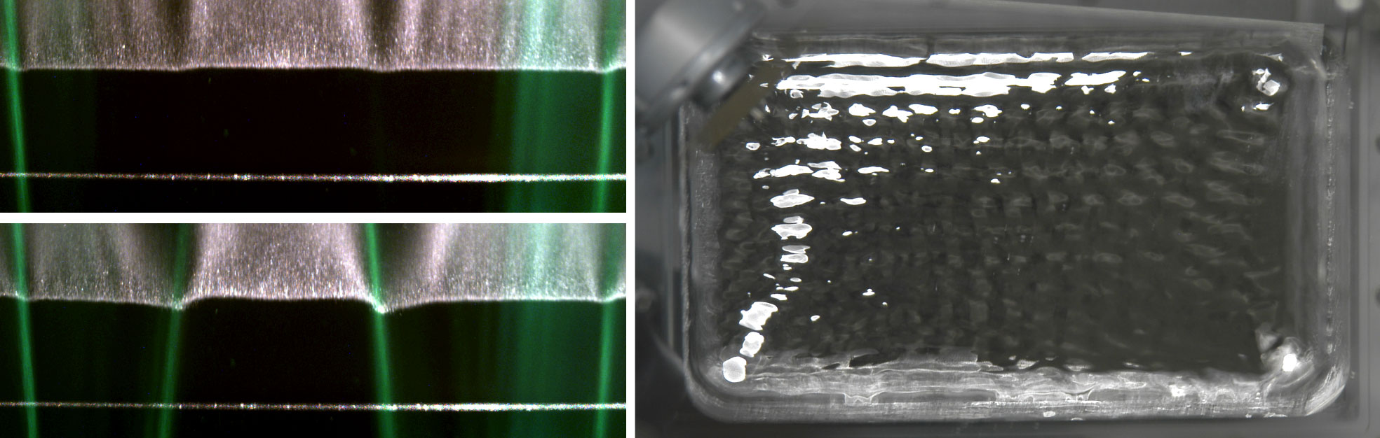
Fig. 2. Height profiles in water and a specular liquid metal model surface GaInSn.
Publications
- S. Gordeev, F. Arbeiter, W.Hering, F. Saverio Nitti, F. Schwab. Analyses of the quench tank configuration for DONES liquid-lithium target system. Fusion Engineering and Design 136 330-334 (2018) doi.org/10.1016/j.fusengdes.2018.02.019
- S. Gordeev, P. Arena, D. Bernardi, P. A. Di Maio and F. S. Nitti. Analytical and Numerical Assessment of Thermally Induced Pressure Waves in the IFMIF-DONES Liquid-Lithium Target. IEEE Transactions on Plasma Science 48(6) 1485-1488 (2020) doi.org/10.1109/TPS.2019.2953614
- S. Gordeev, F. Schwab, F. Arbeiter, Y.Qiu Numerical study of conjugated heat transfer for DONES high flux test module. Fusion Engineering and Design 146 609-613 (2019) doi.org/10.1016/j.fusengdes.2019.01.035
- B. Brenneis, S. Gordeev, S. Ruck, L. Stoppel, W. Hering; Wake Shape and Height Profile Measurements in a Concave Open Channel Flow regarding the Target in DONES. Energies 2021, 14, 6506. https://doi.org/10.3390/en14206506
- B. Brenneis, S. Gordeev, S. Ruck, L. Stoppel, Höhenprofilmessung einer offenen Kanalströmung mit Blick auf das Flüssigmetalltarget in DONES, Proceedings der 28. GALA-Fachtagung “Experimentelle Strömungsmechanik”, 7.- 9. September 2021, Bremen, Hrsg.: A. Fischer, D. Stöbener, C. Vanselow, B. Ruck, A. Leder, ISBN 978-3-9816764-7-1
- B. Brenneis and S. Ruck, Measuring the Surface Profile of a Free Surface Water Flow Regarding the Liquid Lithium Target in DONES, Proceedings 15th International Conference on Heat Transfer, Fluid Mechanics and Thermodynamics, 26.-28. July 2021
HELOKA-US
The HELOKA‑US project aims at studying the DEMO Helium Cooled Pebble Bed (HCPB) Breeding Blanket (BB) Primary Heat Transfer System (PHTS) coupled to an Intermediate Heat Transfer System (IHTS), the so-called DEMO HCPB Indirect Coupling Design (ICD) in a test mock-up (1:1000, ~260 kW).
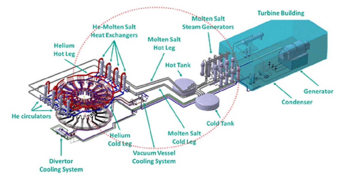
Fig. 1. DEMO HCPB ICD Configuration
The main objectives of HELOKA‑US project are the validation of the decoupling approach (ICD) for DEMO HCPB and the development and qualification of demo-specific technical components (i. e. Helium – Molten Salt Heat Exchanger, DEMO specific helium blower). The planned HELOKA-US test facility enables experimental campaigns replicating the expected modes of operation of the mentioned DEMO concept, namely the power transitions from 2 hours pulse to 10 minutes dwell (P2D) and from dwell to pulse (D2P). Furthermore, regulation strategies to be developed for DEMO will be tested.
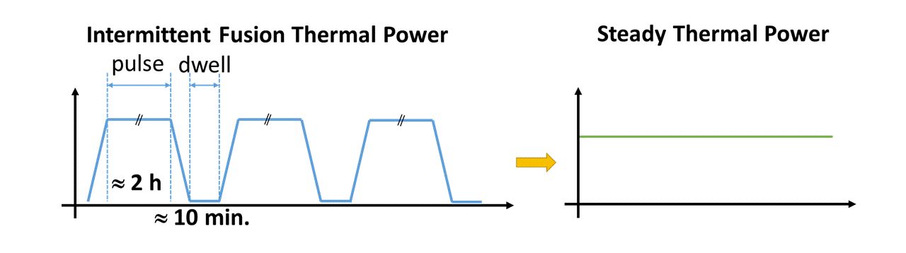
Fig. 2. Schematic goal of HELOKA-US
The HELOKA-US facility consists of three coupled heat transfer loops:
- A high pressure & high temperature helium loop (HELOKA-HP) representing one of the eight DEMO HCPB PHTS;
- A low pressure Molten Salt (MS) loop representing a scaled DEMO IHTS;
- A water cooling loop acting as the heat sink for the MS loop.
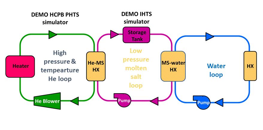
Fig. 3. Conceptual layout of the HELOKA-US test facility
The HELOKA-US facility is partially funded by EU and is under construction at KIT Campus North Building 660.
Publications
- W. Hering, E. Bubelis, S. Perez-Martin and M-V. Bologa., Overview of Thermal Hydraulic Optimization and Verification for the EU-DEMO HCPB BOP ICD Variant, Energies 14, 7894 (2021). https://doi.org/10.3390/en14237894
- L. Barucca, W. Hering, S. Perez Martin, E. Bubelis, et al., Maturation of critical technologies for the DEMO balance of plant systems, Fusion Engineering and Design 179, 113096 (2022). https://doi.org/10.1016/j.fusengdes.2022.113096
- I. Moscato, L. Barucca, E. Bubelis, et al., Tokamak cooling systems and power conversion system options. Fusion Engineering and Design 178, 113093 (2022). https://doi.org/10.1016/j.fusengdes.2022.113093
- S. Perez-Martin, E. Bubelis, W. Hering, L. Barucca. R&D Needs for the Design of the EU-DEMO HCPB ICD Balance of Plant in FP9 // Special Issue Dedicated to 32nd Symposium on Fusion Technology - SOFT2022. MDPI Journal of nuclear engineering, EISSN 2673-4362 / 2022, Vol. 3, Issue 4, P. 435-445. https://doi.org/10.3390/jne3040029
- X. Gaus-Liu, E. Bubelis, S. Perez-Martin, B. E. Ghidersa, W. Hering. Design Features and Simulation of the New-Build HELOKA-US Facility for the Validation of the DEMO Helium-Cooled Pebble Bed Intermediate Heat Transport and Storage System // Special Issue Dedicated to 32nd Symposium on Fusion Technology - SOFT2022. MDPI Journal of nuclear engineering, EISSN 2673-4362 / 2022, Vol. 3, Issue 4, P. 461-472. https://doi.org/10.3390/jne3040032