
HELOKA
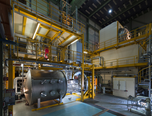
The Helium Loop Karlsruhe (HELOKA) is dedicated for testing fusion reactor components under relevant high heat flux while using high-pressure and high-temperature helium as a coolant. The facility has two helium closed loops:
-
HELOKA-HP for tests up to 500°C and,
-
KATHELO for high temperature experiments (up to 850°C).
The loop has two test sections, each with a vacuum vessel capable of hosting large components. Both tanks have an inner diameter of 3 m and a length of 3 m (cylindrical part) being capable of reaching and maintaining vacuum levels around 10-5 mbar. The High Heat Flux test section (bottom left in Fig. 1) is equipped with an Electron Beam Gun (EBG) having an installed power of 800 kW.
KATHELO and HELOKA-HP share the high heat flux test section, each loop having removable piping connections that can link the loops to the test stand, one at a time.
The helium composition can be monitored during operation using a mass spectrometer (GAM 400 made by InProcess Instruments, Inc., Germany) implemented and integrated into the facility control. In addition to classical measurement capabilities, the facility has a thermal imaging infrared camera and two pyrometers for non-contact temperature measurements. For the high heat flux test section, an X-ray camera allows improved characterization of the EBG heating pattern.
HELOKA-HP
HELOKA-HP is mainly dedicated for testing breeding blanket mock-ups and has the following capabilities:
- Operating pressure from 4 to 9.2 MPa.
- Operating temperature from 100°C up to 500°C.
- Flow rates up to 1.3 kg/s.
KATHELO
KATHELO (Karlsruhe Advanced Technologies Helium Loop) is more oriented towards helium-cooled divertor experiments and has the following capabilities:
- Operating pressure from 4 to 10 MPa.
- Operating temperature from 100°C up to 700°C (the main loop is designed for 850°C but the current connection to the high heat flux test section limits the operating temperature).
- Flow rates up to 250 g/s.
Additional testing capabilities
The facility has two small modular water cooling loops (max. temperature 120°C, one loop operating with 7 m3/h at maximum 2.5 MPa and the other 20 m3/h at maximum 1.6 MPa). These loops can be connected to any of the three test sections.
Recent experiments in HELOKA
Breeding Blanket Experiments
1.1 First Wall Mock-ups
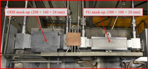
Two First Wall Mock-ups with different surface materials were tested, one with a 2-3 mm ODS (Oxide Dispersion Strengthened) steel plating joined to EUROFER97 steel by diffusion welding; the other one with Functionally Graded (FG) Tungsten/EUROFER97 coating.
[1] Ghidersa, B.-E.; Abou Sena, A.; Rieth, M.; Emmerich, T.; Lux, M.; Aktaa, J. Experimental Investigation of EU-DEMO Breeding Blanket First Wall Mock-Ups in Support of the Manufacturing and Material Development Programmes. Energies 2021, 14, 7580. https://doi.org/10.3390/en14227580
1.2 Safety Experiment (Loss Of Flow Accident)
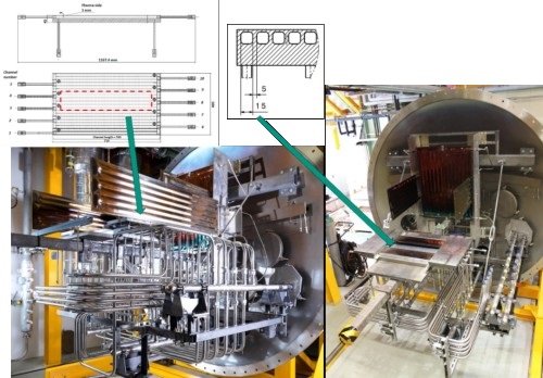
A prototypical set-up simulating a LOFA (Loss Of Flow Accident) situation in a helium-cooled breeding blanket First Wall (FW) mock-up under typical heat load conditions was tested. The objectives were: (i) reproduce the expected DEMO thermal-hydraulics conditions during normal and off-normal situations to test different thermal-hydraulics issues and coolant flow strategies, and (ii) provide robust data for the design and safety analyses with numerical codes. The FW mock-up was a P92 steel plate with 10 cooling channels.
[1] Ghidersa, B.-E.; Gonfiotti, B.; Kunze, A.; Di Marcello, V.; Ionescu-Bujor, M.; Jin, X.Z.; Stieglitz, R. Experimental Investigation of a Helium-Cooled Breeding Blanket First Wall under LOFA Conditions and Pre-Test and Post-Test Numerical Analysis. Appl. Sci. 2021, 11, 12010. https://doi.org/10.3390/app112412010
1.3 Indian Test Blanket Module (TBM) First Wall testing
HELOKA is open for cooperation. In 2017, following a contract with Institute for Plasma Research (IPR in Gujarat, India), a TBM First Wall mock-up was tested [1]. Both normal and accidental operating conditions were investigated.
[1] S. Ranjithkumar et al, Performance assessment of the Helium cooled First Wall mock-up in HELOKA facility, 2020, https://doi.org/10.1016/j.fusengdes.2019.111319
1.4 Monitoring Coolant Gas Composition at TBM-Like Operating Conditions
In parallel to the experiment described above in 1.1, the gas flow was monitored with the mass spectrometer. An accuracy of 1 ppmv or lower is reachable. Measurements are reproducible and can be automated. The measurements showed that the loop filling procedures ensure that the helium stream in HELOKA has a low level of impurities in the range of 0.02 % even after long time operation.
R. Krüssmann, B.-E. Ghidersa, Monitoring coolant gas composition at TBM-like operating conditions, Fusion Engineering and Design 166 (2021) 112300, DOI: https://doi.org/10.1016/j.fusengdes.2021.112300
Helium-cooled Divertor Experiments
KIT has a long history in developing helium-cooled divertor solutions. The Helium-Multi-Jet (HEMJ) finger concept was the first that demonstrated experimentally that such a solution could withstand heat fluxes up to 14 MW/m².
Following this tradition, under EUROfusion, the concept was developed further. Thus, instead of using the smaller 9-finger modules as previously proposed, the present concept proposes a target made out of toroidal parallel cooling elements, each individual element having the same length as the target poloidal length and a thickness of 23 mm in toroidal direction. The armour is made out of tungsten slabs of similar shape as the EUROfusion baseline solution (water-cooled, ITER-like, target) that are brazed on the heat sink pipe/vessel.
The coolant (helium) is entering the target element trough a distribution manifold installed inside the laminate pipe. The manifold is made out of 5 segments, each segment being 130 mm long. The helium flows inside each segment exiting through the hole-pattern on the side of the manifold, thus cooling the containing pipe. After impinging on the heat-loaded face of the pipe, the helium flows inside the next segment. The helium flow rate is calculated in such a way that each cooling segment can withstand 10 MW/m² on the surface.
[1] M. Zhao, B. Ghidersa, R. Stieglitz, CFD evaluation and optimization of the HEMJ divertor cooling design, Fusion Engineering and Design, Volume 158, 2020, 111669, https://doi.org/10.1016/j.fusengdes.2020.111669
[2] Joon-Soo Lim, Namkyu Lee, B.-E. Ghidersa, Hyung Hee Cho, Enhancement of cooling performance of a helium-cooled divertor through the addition of rib structures on the jet-impingement area, Fusion Engineering and Design, Volume 136, Part A, 2018, 655-660, https://doi.org/10.1016/j.fusengdes.2018.03.048.
[3] Namkyu Lee, Joon-Soo Lim, B-E. Ghidersa, Hyung Hee Cho, Nozzle-to-target distance effect on the cooling performances of a jet-impingement helium-cooled divertor, Fusion Engineering and Design, Volume 136, Part A, 2018, Pages 803-808, https://doi.org/10.1016/j.fusengdes.2018.04.012
SIRHEX
The SIRHEX facility (Surface Infrared Radiation Heating Experiment) is a medium heat flux facility using infrared tubes as heat source.
The test chamber, a vacuum vessel with a diameter of about 1.8 m, can operate at pressure levels as low as 10-3 mbar, and it can host mock-ups with a length of maximum 700 mm. The mock-ups can be cooled by water or by Antifrogen N.
In the facility, heat fluxes up to 500 kW/m² can be achieved. However, at this high heat fluxes, the lifetime of the heaters is low [1]. The experiments showed that it is possible to operate at 300 kW/m² for long time without a drop in performance or deterioration of the infrared heaters [2].
On behalf of the Institute of Plasma Physics in Garching, the new design of the pumping gap panels for Wendelstein 7-X was validated in this setup [3].
[1] A. Kunze, B-E. Ghidersa, F. Bonelli, SIRHEX—A new experimental facility for high heat flux testing of plasma facing components, 2015, https://doi.org/10.1016/j.fusengdes.2015.01.026
[2] A. Kunze, B-E. Ghidersa, Model-based optimization of the heat flux distribution of IR-heaters for high heat flux testing, 2017, https://doi.org/10.1016/j.fusengdes.2017.05.130
[3] Jean Boscary, Felix Schauer, Bradut-Eugen Ghidersa, Regina Krüßmann, Martin Lux, Michael Czerwinski, Zhongwei Wang, Chuanfei Li, Boris Mendelevitch, Gunnar Ehrke, Thermal loading test of a Wendelstein 7-X pumping gap panel. Fusion Engineering and Design 175 (2022) 112986. https://doi.org/10.1016/j.fusengdes.2021.112986
HEMAT
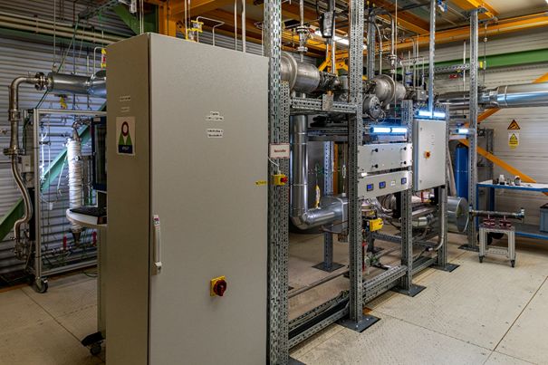
HEMAT Fig.1: Cold part.
The Helium Loop for Materials Testing (HEMAT) is a smaller loop, independent from the HELOKA facility, though it shares the cooling circuit with KATHELO. The loop is intended for corrosion experiments on newly developed materials under high temperature conditions and controlled atmosphere.
HEMAT presents the following operating conditions:
- Temperatures up to 650°C.
- Mass flow max. 20 g/s (max. 5 g/s in the high temperature section).
- Operating pressure 3 - 4 bar.
- Partial pressures of impurities are adjustable (e.g. oxygen, hydrogen in small quantities).
- HEMAT disposes of a humidifier and a desiccant column, so that the humidity in the helium can be adjusted.
HEMAT is connected to a mass spectrometer to analyze the gas composition. It is intended to run 24/7 without operator surveillance, so long-term experiments are possible.
In the recent past, EUROFER samples provided by the Institute of Applied Materials were investigated in HEMAT [1].
[1] R. Krüssmann, B.-E. Ghidersa, M. Walter, Thi Tra My Nguyen, V. Weber, P. Heger, F. Arbeiter, G. Schlindwein, G. Zhou, F. A. Hernández Gonzalez, Experimental investigation of the corrosion behavior of Eurofer97 steel in contact with Lithium ceramic breeder pebbles under specific Helium Cooled Pebble Bed breeding zone atmosphere. Fusion Engineering and Design, Volume 201, April 2024, 114314.

HEMAT Fig.2: Hot part with the test section.