
Magnet Safety
1. Quench
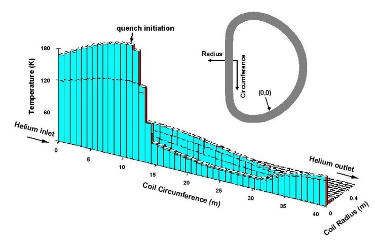 |
| Temperatures in a pancake some time after quench initiation. A pancake here means a conductor being wound like shown in the small figure below. The inlet of the cable is at radius 0 m and circumference 0 m. The exit is in the outermost turn at circumference 41 m. Two turns of the pancake are affected by the quench that was initiated at circumference 11 m in turn 1. From there the front has propagated towards the inlet. The propagation downstream however is hindered: Turn to turn heat conduction lead to another pair of quench fronts in turn 2. While the downstream front of turn 2 evolves normal the upstream quench front of turn 2 presses against the downstream front of turn 1. In this way a cold slug of Helium is trapped from about 15 m to 30 m circumference of turn 1 |
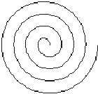 |
| Schematic of a “pancake” like wound conductor |
2. Shorts in a coil
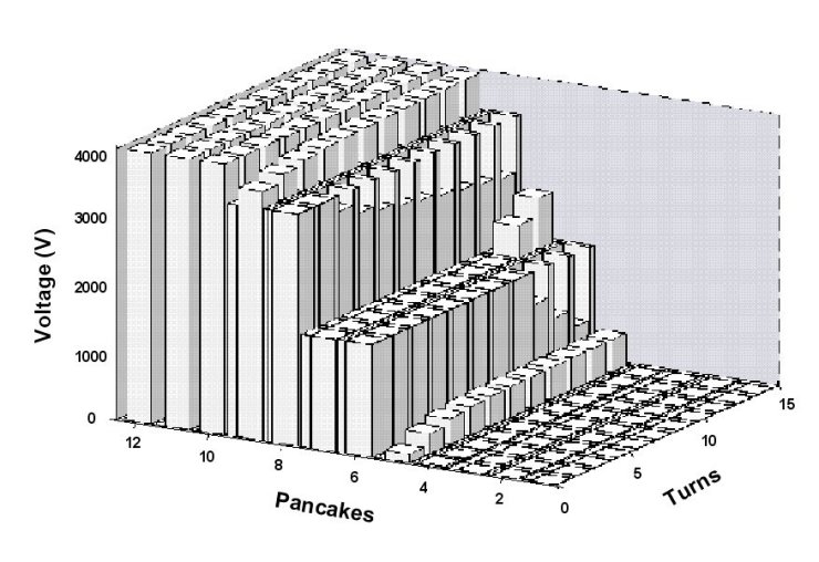 |
| Voltage in a cross section of a coil which has some insulation failure. The characteristic of the coil is that two pancakes are built into groves in one radial plate. In case of insulation failure the current can flow from the first mesh element with failed insulation towards the last mesh element with failed insulation through the radial plate. From the figure it is to be seen that the insulation for pancakes 6/7 and 8/9 failed but the insulation between the radial plates is still intact. At positions where the cable cross section shows a higher or a lower voltage than the radial plate the insulation is intact. This means insulation failure is located at turn 8 of pancake 6, at turn 9 of pancake 7 and at turn 1 and 2 of pancake 8. The conductor in the first four pancakes is still superconducting |
3. Loss of vacuum of the magnet cryostat
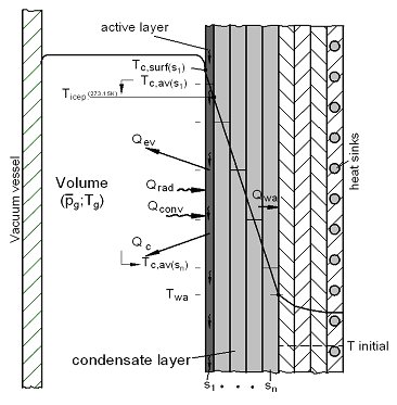 |
| Sketch of the multilayer condensate model in MAGS to investigate condensation and evaporation processes on cold magnet structures in case of air, helium or steam leaks in the magnet cryostat. |
4. High power arc behavior at coil power supply lines
High power arcs at the power supply lines (busbars) of large coils as the ITER toroidal field (TF) coils may have the capability to burn holes into metal shielding like the cryostat wall. This phenomenon takes place outside the MAGS coil grid and therefore needs additional modeling. Arc behaviour along uninsulated rails has been widely investigated in the field of electric switchgears, however little is known about arcs along insulated conductors. As the velocities are much lower and the distances are larger, a direct modeling of a high power busbar arc with e.g. a finite element model is beyond the present calculation capacities with regard to calculation time requirements. For this reason a phenomenological modeling oriented on model experiment results seems an appropriate way to describe high power arcs at the busbars of large coils. Such a model is under development. It bases on the available MAGS capabilities and is realized formally as a new MAGS subroutine called BUSARC. BUSARC development proceeds in very close orientation to the VACARC experiments that are underway at INR in parallel to the modeling approach in different scales from 1:7 to 1:3 vs. ITER. Further experiments for the validation of BUSARC are required. The final target is an extrapolation of BUSARC for its application at ITER full scale.
5. Physical phenomena under investigation
- Modeling of arc behavior at coil power supply lines supported by small experiments
- Modeling of steam condensation and evaporation at cryogenic surfaces
- Experiments to insulation failure behavior up to steel melting temperature
Supporting experiments